Crossing wet and dry gaps for any military requires engineering know-how and sufficient suitable bridging equipment and systems to span the numerous gaps that will be encountered in a major conflict.
Military bridging is high on the agenda of many allied militaries across Europe, with programmes and projects underway and established processes and test protocols in place defining what is required if a bridging system is to be adopted and deployed. This article looks at design and test code aspects for military bridging systems, the status of a current gap-crossing competition underway in the UK, along with certain significant industry and military unit milestones and developments.
Bridging Need Scene Setting
Across the European theatre of operations, dry and wet-gap obstacles, from streams and tributaries to major rivers such as the Danube, the Rhine and the Elbe, as well as dry gullies and gorges, present the armies of NATO and its allies with the challenge of being able to deploy sufficient tried and tested bridging capabilities, should the need arise, to move any and all equipment and vehicles needed over such obstacles and onwards to wherever the front line of any future conflict in Europe might be.
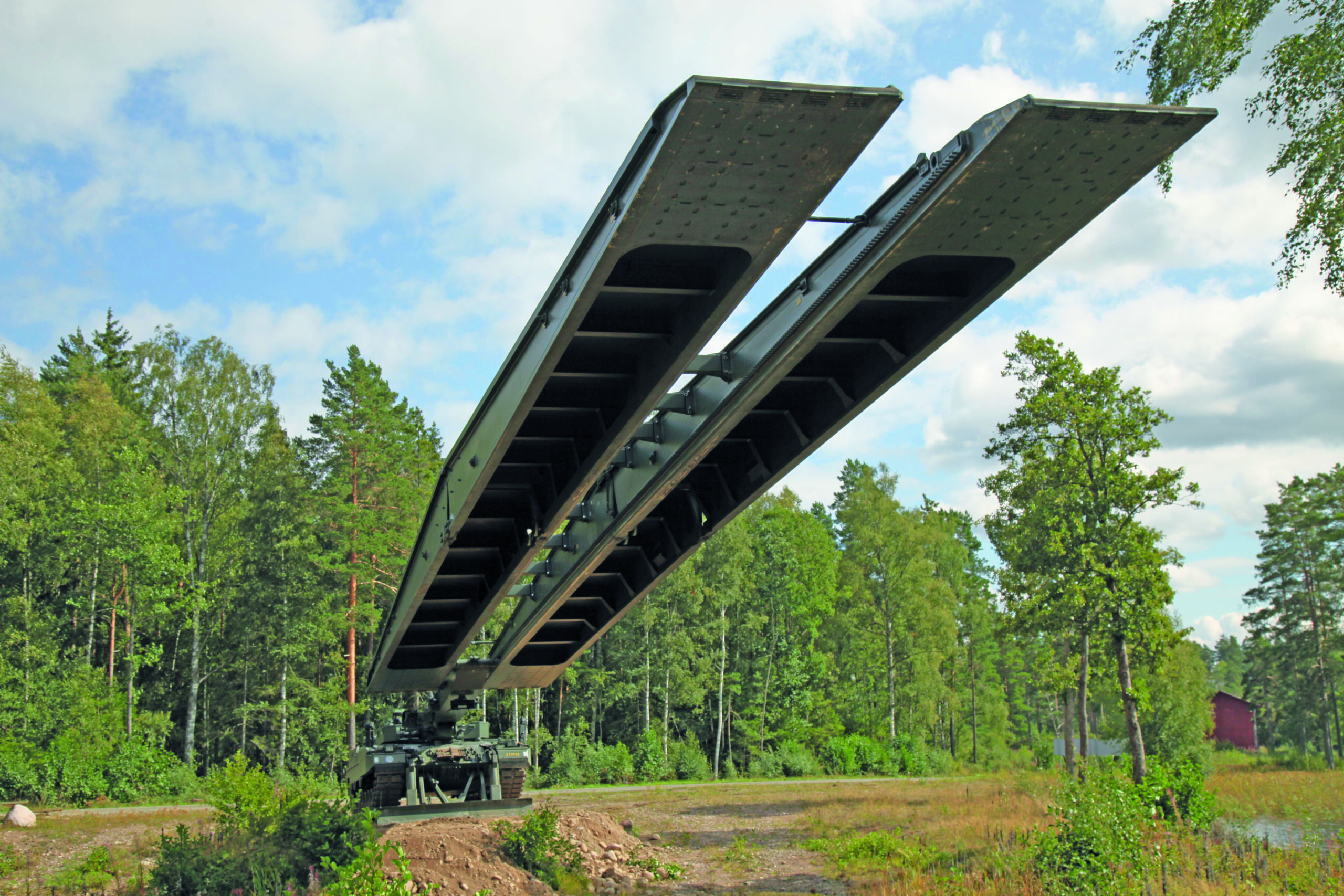
While there is a wide variety and some highly capable bridging systems currently in use within NATO, such as the M3 rig, improved ribbon bridging equipment, medium girder bridging, Armoured Vehicle Launched Bridge (AVLB), the Leguan bridge layer to name but a few, the quantity of such systems, according to certain engineer general staff within NATO, is below what would be needed to span all the obstacles an allied army will encounter moving back and forth across Europe in a conflict, were even a fraction of the bridges spanning rivers and gaps degraded or destroyed.
And even with bridges intact, many will be unable to support the tonnage of modern tanks whose Military Load Classifications (MLC), often between MLC 80 and MLC 95, far exceed those of their ancestors whose tonnages were more than adequately handled by most of Europe’s bridges built since WW2, which can mostly cope with vehicles up to MLC 70.
To meet this challenge NATO and its allies need urgently to increase the quantity of bridging systems available and, at the same time, make sure new systems conform to, and meet, stringent and established requirements to ensure they are up to the job.
Ensuring Needs Are Met
First published in 1974, the latest update to the ‘Trilateral Design and Test Code (TDTC) for Military Bridging and Gap-Crossing Equipment’, prepared for the design and testing of mobile military bridges and launch mechanisms and agreed between Germany, the UK and the US, was issued in March 2019. It is intended to ensure all bridging and gap-crossing equipment coming into service with these nations’ armed forces is designed and made in accordance with a standard set of loading, design and test parameters, as well as accepted materials, so that any new bridging system will, ultimately, meet user needs and can be readily manufactured.
Prepared by the Design and Analysis Group for Military Bridging and Gap-Crossing Equipment, the TDTC covers a wide array of such subjects as clear-span and combination bridging, pier support requirements, floating bridges and rafts, as well as looking at typical vehicle data that needs to be taken into account for design purposes and topographical matters when it comes to a physical gap or crossing and how factors such as temperature, local environment, altitude and anchorage available to crossing equipment must be considered in design and testing regimes. Loads and load combinations have also to be factored into equipment design to cover as many eventualities as might be encountered in any sudden or spontaneous operational eventuality.
On the safety side of things, the TDTC explores safety coefficients and fatigue factors relating to metals, composites and adhesives used in the manufacture of bridging equipment, as well as looking at operational safety issues such as floatation and stability, avoiding rotation and overturning and how anchorage points must be secure to avoid lifting. Systems’ ability to be able to tolerate and withstand a degree of damage sustained during deployment or under enemy fire without becoming inoperable is also set out in the document with testing regimes to address all these areas and more.
The TDTC goes into great detail on a wide range of matters, from floating bridges and rafts, to specific sub-systems such as hydraulics that can be affected by altitude impacting launch and retrieve times, sometimes to such as extent that in extreme altitudes, bridge launch and retrieval may not be achievable. On the subject of combination bridging, for example, it states that this may be used across wet or dry gaps in situations where the clear span to be bridged exceeds the span capability of a single bridge system, thereby requiring two as a potential solution. That said, across wet gaps, the use of combination bridging on water is only permissible, according to the TDTC, under conditions where the maximum surface water speed at mid-stream does not exceed 1.5 m/s (2.9 knots). It can also only be used where, under its own weight (i.e. without any vehicles or other additional live weight crossing), the water level does not come within 100 mm (4 in) of any trafficable deck surface. The TDTC also stresses that combination bridges must not be launched without some form of non-metallic interface between the bridges in order to spread the anticipated live load and prevent slipping between metallic surfaces in wet conditions and under live vehicle trafficking where vibration along with vertical and sideways forces will be present.
The TDTC for Military Bridging and Gap-Crossing Equipment includes extensive data sheets documenting metallurgical aspects and requirements of aluminium and steel for the manufacture of equipment, as well as detailed appendices with relevant force, weight, density, velocity, slope, pressure and other conversion tables tailored to the specific tasks of bridging and gap crossing. Its Appendix C, for example, sets out comprehensive and illustrated, tabulated details of the characteristics of hypothetical vehicles used for the rating of vehicle and bridge MLC in SI units. Latest data on composite and adhesive materials are also detailed in the TDTC’s appendices.
UK Seeking an Autonomous Solution
While the TDTC addresses a plethora of traditional bridging and gap-crossing issues and equipment, a key operational challenge facing all engineers is that of recon for suitable crossing places. This is the subject of a current project in the UK, which has recently entered Phase 2. Launched in February last year when the UK MoD officially began Phase 1 of its Map the Gap project in which Defence and Security Accelerator (DASA) set out to find ideas for an ‘autonomous’ gap and water-crossing solution that addresses the dangers faced by engineers when conducting reconnaissance to find suitable crossing points. Such recce typically involves surveying both sides/banks of a wet gap or river, which not only exposes troops to potential enemy fire, but can also jeopardise the location’s suitability as a crossing point if enemy forces pick up on the interest shown by the recon engineers. The project, run on behalf of the Defence and Science Technology Laboratory (DSTL), stated the wet gaps considered in the project to be as much as several hundred metres wide.
Enter project ‘Map the Gap’; its aims include the removal of personnel from the recce task and, instead, envisage a semi-autonomous remote system that can conduct the required survey activities for either bank of a water gap and collect measurements of the potential crossing locale, but without deployment of personnel. This not only protects troops, but also provides the chance of more potential crossings being surveyed.
Four Phase 1 challenges had to be addressed by any solution proposal. Challenge 1 was to measure the ground bearing capacity of the far bank of a wet gap obstacle, by taking an average of five readings with a tolerance of +/-50 kPa. Challenge 2 was to produce a bank height profile of the far bank contact zone, encompassing up to 2 m below the minimum waterline and 8 m inland of the bank edge. The profile to be produced with a minimum horizontal resolution of 10 cm and vertical tolerance of +/-1 cm. Challenge 3 was to measure the gap width (between banks, with a tolerance of +/-5 cm) and the vertical difference in bank heights with a tolerance of +/-2c m and any proposals had to be able to cope with banks up to 300 m apart. And challenge 4 was to measure the local flow rate of a river and produce a full riverbed profile for water depths of up to 3 m, and river widths up to 300 m.
Phase 1 contracts lasted about 10 months, with five SMEs funded to develop and test their solutions with the MoD, and culminated in a two-week demonstration of the systems – built to technology readiness level (TRL) 5 – Technology basic validation in a relevant environment – at a wet-gap site in the UK. The total funding for the Phase 1 bids was £1.2M. A drone-mounted system using electromagnetic scanning was put forward by Scytronix; Wight Ocean demonstrated a bottom-crawling amphibious system; unmanned aerial system sensors along with data analysis capabilities were demonstrated by Nordic Unmanned; Digital Concepts Engineering demonstrated a combined UGV/UAV platform comprising multiple sensors for data acquisition, processing and presentation; and Foundry Cube partnered with Ultrabeam Hydrographic demonstrated an autonomous, amphibious, hydrographic survey vehicle, using sonar, lidar and other technologies to deliver results.
Now, Map the Gap has entered Phase 2 and in July £2M in contracts were awarded by DASA to three SMEs to develop semi-autonomous reconnaissance and survey systems in line with Map the Gap requirements. The three small and medium-sized businesses awarded the Phase 2 funding to fast-track their innovations for testing with the British Army are: Digital Concepts Engineering awarded £982,791 to develop a proposed low-signature, autonomous-unmanned air and ground system with a capability to deploy sensors to collect the desired gap measurements; Ultrabeam awarded £498,075 to develop its ARGONAUT 2 product, an autonomous and amphibious, kinematic survey vehicle that includes a modular survey sensor package with LiDAR, sonar, current profiler and electric cone penetrometer. Autonomy is also enhanced by implementing AI Machine Learning technology; the third SME is ISS Group awarded £514,727 to further its UAV rotorcraft equipped with 3-D photogram metric, EO/IR and downward viewing IR cameras, offering a simultaneous localisation and mapping sensor, ground penetrating radar and bathymetric / topographic LiDAR.
Assistant Head Manoeuvre Support and C-CBRN, Capability Directorate, Army Headquarters, Colonel Sam Stuthridge OBE, said that DASA had elected to take forward these three UK contenders into the next phase of the study and to accelerate the selected technologies through further trials and experimentation in order to achieve a world-class product, one with utility within manoeuvre support, but also across wider defence capabilities. He added, “Map the Gap will directly support Project TRITON – a next-generation amphibious bridging system being jointly procured with the German Army.”

