


Identification Friend or Foe (IFF) technology helps to prevent fratricide. How does this technology work and how has it evolved since its development over eight decades ago?
For the United Kingdom, the Second World War almost started with an acute military embarrassment. The governments of France and the UK told Germany to cease military operations on 3 September 1939. The Nazi regime had invaded Poland two days before. At 11.12 British Summer Time (10.12 Greenwich Mean Time) air raid sirens wailed over London. Writing in his diary, the then First Lord of the Admiralty Winston Churchill recorded that “there were planes in the sky. Whose, we could not be sure.” It would be another 370 days until the Luftwaffe (German Air Force) would drop its first bombs on the British capital. Mr. Churchill, along with millions of other Londoners had heard a false alarm. This was triggered by an Armée de l’Air (French Air Force) aircraft bound for RAF Northolt airfield in West London. The crew had failed to file a flight plan informing the British of the plane’s arrival. Fortunately, the aircraft landed safely unscathed by Royal Air Force (RAF) fighters or British Army anti-aircraft guns.
Chain Home
The incident did, however, highlight the risk of mistaken identity to aircraft. Four years previously, Scottish engineer Robert Watson-Watt have proved the viability of radar. Mr. Watson-Watt and his assistant Arnold Wilkins demonstrated that radio waves could detect and track aircraft. This was done during an experiment performed from a field near Daventry, central England. Radar was undoubtedly a breakthrough. Aircraft could now be tracked in all weathers, day or night, beyond the range of the human eye.
Radar was instrumental to the RAF’s victory in the Battle of Britain in summer of 1940, but it had a shortcoming. A radar could detect and track an aircraft providing information on its range, speed and altitude but provided no details on the aircraft’s identity. The RAF’s AMES Type-1 Chain Home (CH) radar system used frequencies of between 20 MHz and 55 MHz.
These frequencies are comparatively low compared to those used today by ground-based air surveillance radars. As such, while they provide the information detailed above, their wavelengths do not provide a good, detailed picture of the aircraft. Higher frequencies like X-band (8.5 GHz to 10.68 GHz) were unavailable during the Second World War. These wavebands can indicate aircraft type based on its radar cross section (RCS). Alas, this was not possible with the Very High Frequency (VHF) transmissions of Chain Home.
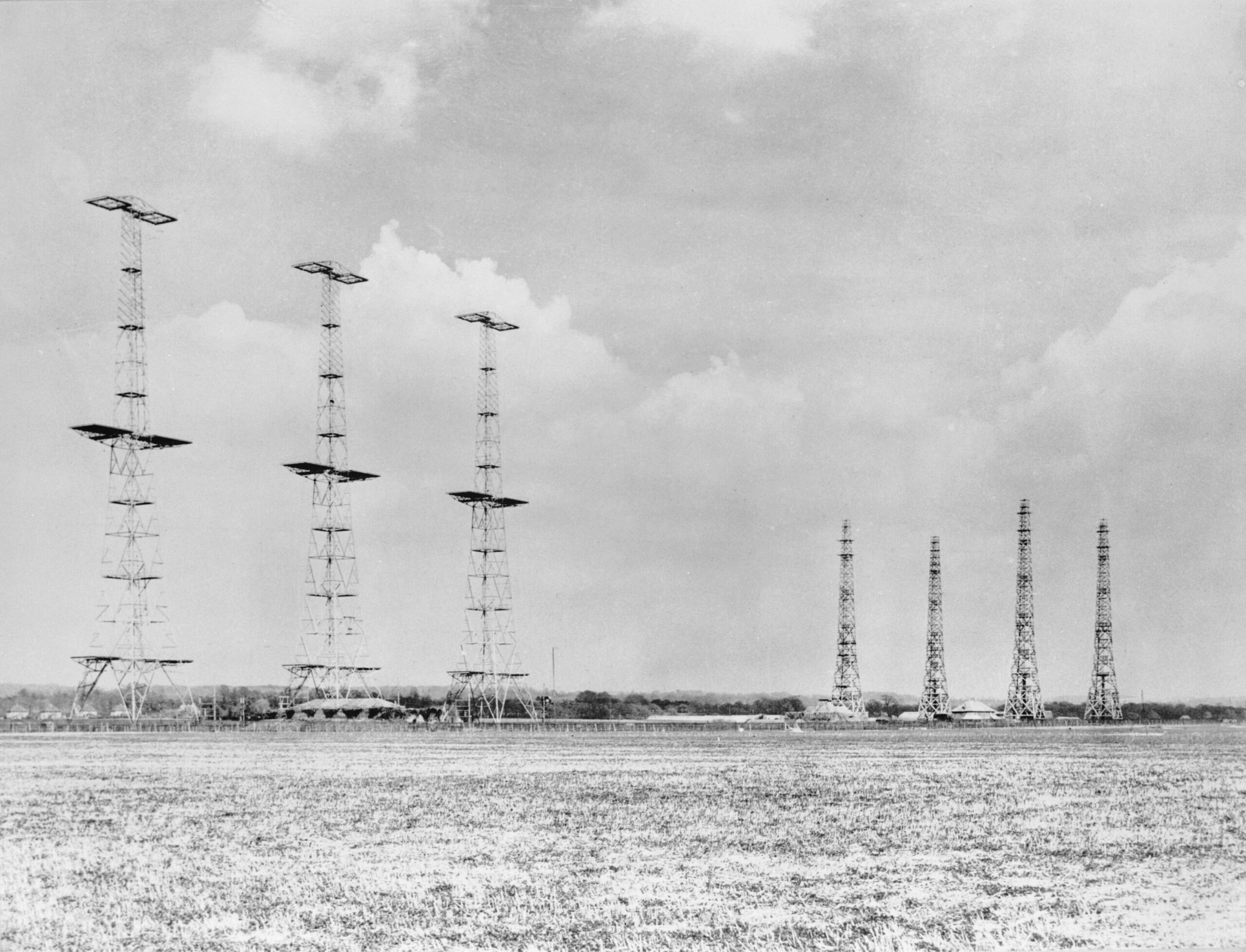
Credit: Imperial War Museum
Shooting down the wrong aircraft is an expensive mistake in blood and treasure. It is probably impossible to eliminate all incidents of friendly fire during air operations, or indeed in warfare writ large. Nonetheless, efforts must be taken to reduce its likelihood. A solution was found in the form of Identification Friend or Foe (IFF), which was pioneered by both Britain and Germany using similar principles. In Britain, IFF was Mr. Watson-Watt’s brainchild. An initial IFF system was trialled but found to have shortcomings – when the aircraft was broadside to the radar it returned a strong echo on the radar screen, but this was not the case when the aircraft presenting its forward or aft aspect.
These shortcomings led to further developments yielding a system unimaginatively called the IFF Mark I (IFF Mk.I) introduced in 1939. This was built around a radio receiver tuned to the CH’s transmission frequencies. When the receiver detected an incoming CH radar signal it would transmit an amplified version of that signal back to the radar on the same frequency. The result was that the radar operator would see a very strong radar target on their display which was the friendly aircraft. IFF Mk.I was very simple – an aircraft returning a strong signal was a friendly, and one which did not was unknown, hence possibly hostile. Nonetheless, IFF Mk.I had shortcomings, the main one being gain. Put simply, gain is the amount of transmission power a radio or radar can send in a particular direction. The problem for IFF Mk.I was that its gain had to be continually manually adjusted to ensure it stayed working. The system was only sensitive to one radar transmission frequency, which meant it had to be retuned every time a new transmission frequency was encountered. Setting these parameters in flight added to the pilot’s workload. A 2003 article by the late radar engineer Richard Trim in Measurement and Control remarked on how the author “had the experience of trying to set this control under laboratory conditions and found it quite difficult.”
IFF Mk.I would soon be overshadowed by IFF Mk.II/N entering service a year later. This introduced an automatic gain control ensuring the gain remained consistent. The equipment also continually scanned radar wavebands looking for an incoming friendly radar transmission. Once detected, the IFF signal was sent. IFF Mk.II/N could also cover the 200 MHz frequency bands of the AMES Type-2 Chain Home Low (CHL) low-altitude radars introduced from 1939 ,and radars being introduced by the Royal Navy. These changes brought a high level of automation to the RAF’s approach to IFF, helping reduce the crew’s work burden.
Indicative of the pace of innovation in wartime, a radically different approach to IFF was pioneered from late 1940 by British radar expert Dr. Frederic Williams. His idea was to have what Mr. Trim called a ‘separate band’ IFF system. Dedicated transmitters sent out a pulsed IFF interrogating signal on a frequency of 150 MHz. The pulses of the interrogating signal were synchronous with the pulses of the radar equipped with this IFF. This allowed the correlation of the aircraft’s radar echoes with its IFF ‘reply’. Thus, the radar operator would immediately see that a particular target was friendly. Moreover, this new IFF Mk.III system’s gain was stabilised and needed no manual adjustment from the crew. It entered service in 1941 and even became the basis for the standard IFF system used by the US Navy, known both as IFF Mk.IV and ABK. In RAF service, IFF Mk.III continued to be used some time after the Second World War.
IFF research continued, and in late-1943 Canada, the UK and US pooled their IFF development efforts into the United Nations Beaconry initiative. This worked on an IFF system which could accept interrogations and replies on frequencies of 950 MHz to 1.260 GHz. In 1945, the end of the war in the Pacific brought this work to an abrupt end.
Nonetheless, the US Navy continued development of what would have become known as IFF Mk.V with the design coming to fruition in 1951. IFF Mk.V could send out three distinct challenges known as Mode-1, Mode-2 and Mode-3/A. These modes differed by the octal response sent by the aircraft when challenged. The octal numbering system uses eight digits of 0, 1, 2, 3, 4, 5, 6 and 7. A Mode-1 interrogation will cause the aircraft to transmit a two-digit octal. Each digit of this code would match the aircraft type with its mission, for example, ‘Bomber, Training’. Mode-2 was like Mode-1 but used a four-digit octal code for responses. Both these modes were reserved for military use. Mode-3/A also used a four-digit octal code, but it was also used by civilian aircraft.
Secondary Surveillance Radar
Post-WWII, pioneering IFF work during the conflict triggered the development of Secondary Surveillance Radar (SSR). SSR is used extensively for civilian and military Air Traffic Control (ATC), and is almost identical to the philosophical underpinning of IFF. An aircraft has a transponder and an SSR collocated with a standard primary air surveillance radar sends out a challenge on a frequency of 1.030 GHz. This is received by the aircraft’s transponder which transmits its reply on a frequency of 1.090 GHz. Like IFF, the transponder provides details of the aircraft’s identity. This takes the form of a four-digit octal ‘squawk’ given to an aircraft by an air traffic controller. The transponder also transmits details of the aircraft’s altitude taken from its altimeters. Like other air surveillance radars, these can only detect an aircraft as a target on a screen. SSRs are indispensable to providing the controller with information on the aircraft’s identity.

Credit: CSG Aerospace
IFF development continued and by the mid-1950s, plans were afoot to replace IFF Mk.V with the new IFF Mk.X standard. IFF Mk.X was adopted by military and civilian aircraft alike. Among the enhancements introduced for IFF Mk.X was an expansion of the codes relayed by the aircraft transponder. IFF Mk.X relayed four A, B, C and D codes. Mode-A corresponded to the Mode-3/A response of IFF Mk.V, Mode-B was mostly used by British and French civil ATC, while Mode-C encoded the aircraft’s altitude information in 100 ft (30.5 m) increments via a four-digit code. Mode-D was developed to allow some expansion of IFF Mk.X if required, an addition which was never needed. Over time, Mode-B’s use declined in favour of Mode-A for military and civilian ATC while Mode-C was used for altitude reporting.
One shortcoming with IFF Mk.X which was also present in the earlier IFF versions was that neither the interrogation nor response was encoded, which was a significant problem for militaries. Hostile IFF interrogators could transmit a challenge and triangulate an aircraft’s position via its response. IFF Mk.X attempted to introduce a modicum of security by using a two-pulse method. IFF interrogation had hitherto been based on a single pulse interrogation signal sent to the transponder, and with the reception of this pulse triggered the transponder’s response. The reason why a single pulse was used was because the trigger for the response was the radar signal itself. The introduction of dedicated SSRs and military IFF interrogators, which performed a similar task, rendered this unnecessary.
Instead, two pulses on a specific frequency with specific timing were transmitted. The transponder would be tuned to only accept interrogations of these specific timings and frequencies. If a hostile interrogator did not match these characteristics, the transponder would not respond. If the challenge did, the transponder replied with a single pulse.
Mode-4
The next significant development in IFF’s post-war history was the adoption of Mode-4 in the mid-1960s. This provides a three-pulse reply to an encrypted challenge, although this was only used by the US military. As Mr. Trim’s article noted, researchers at the UK’s Royal Signals and Radar Establishment (RSRE) flagged concerns over its technical integrity.
Moreover, European NATO members had concerns over dependence on the US National Security Agency (NSA), which was the sole source of the cryptographic computers needed to run Mode-4. As Mr. Trim notes, the technical concerns flagged by the RSRE were taken onboard by USS IFF experts. Remedies were made in the form of the IFF Mode-4 Technical Improvement Programme.
A major problem for NATO as the 1970s unfolded was that alliance members were using a hodgepodge of differing IFF systems and protocols. There was a distinct need across the alliance to harmonise and standardise how IFF was being employed. The result was NATO’s Next Generation IFF programme which introduced the IFF Mk.XII standard accommodating the Mode-S, Level-3 and Mode-5 protocols.
Mode-S/Mode-5
Mode-S was a major step forward. Firstly, it stopped the excessive interrogation of transponders which could be a problem in areas where several ATC radars operated. It also allowed the protocol to share information from an aircraft’s Traffic Collision Avoidance System (TCAS). This helped reduce risks of mid-air collisions. TCAS information was shared from one aircraft’s transponder to others in the aircraft’s locale. Basically, TCAS is a way of saying ‘I’m here’ to other aircraft nearby. Usefully, Mode-S also assigns each aircraft carrying the system to transmit its call sign and a unique address to SSRs. The address is a 24-bit identifier assigned by the International Civil Aviation Organisation (ICAO), and is specific to each aircraft. This is like the internet protocol address of a computer. The address is sent by the transponder as a response to a Mode-5 interrogation. It is displayed on the air traffic controller’s radar screen as a six-digit hexadecimal code. Hexadecimal code uses 16 symbols from zero to nine and A to F.
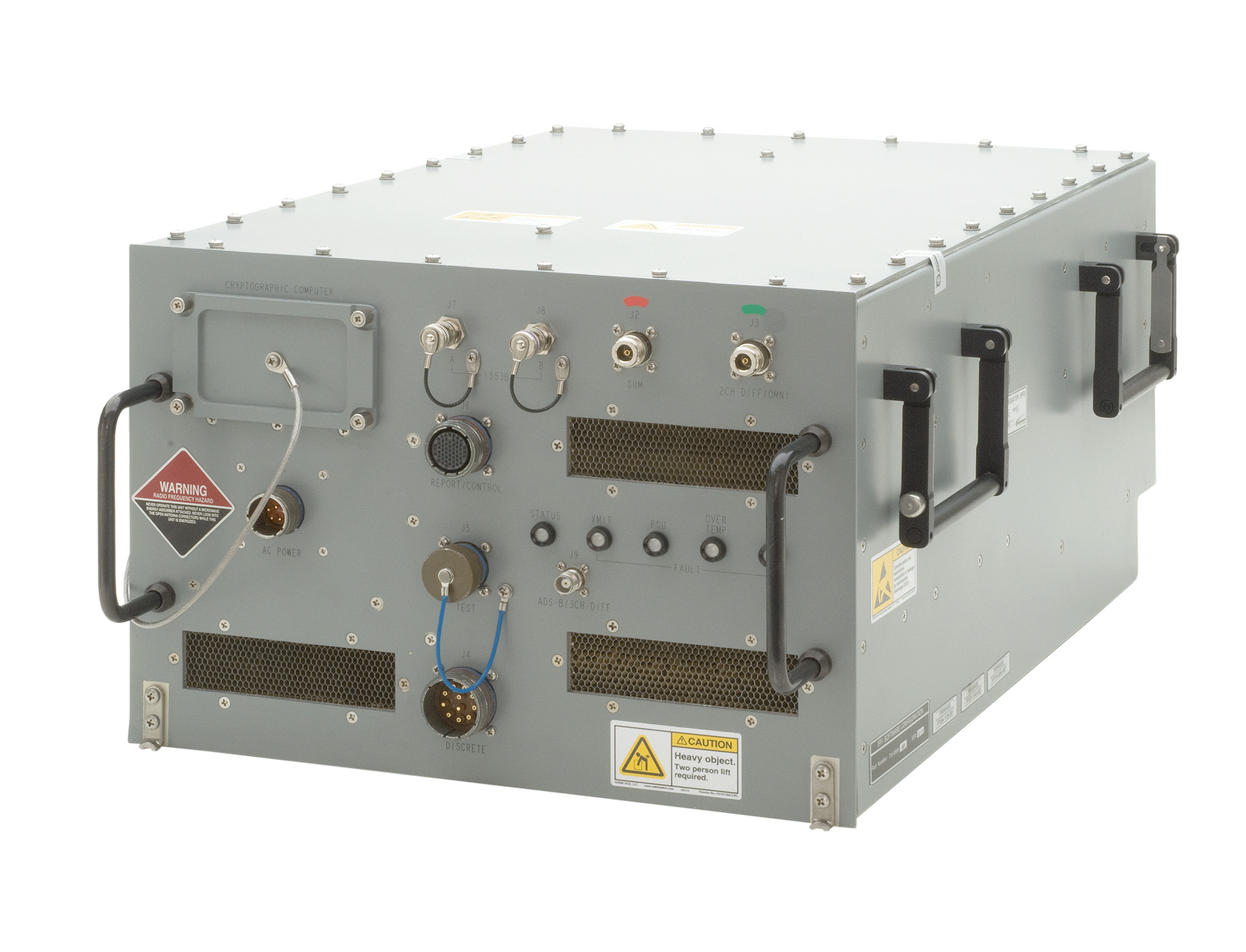
Credit: Telephonics
Mode-5 is the cryptographically secure version of Mode-S for the military. Work commenced to adopt Mode-5 across NATO in 1995. The US Joint Chiefs of Staff ordered a new IFF protocol to replace the IFF Mk.XII Mode-4 system. As a result, in 2002 NATO ratified Standardisation Agreement 4193 (STANAG 4193), which introduced IFF Mk.XIIA Mode-5 as the alliance’s standard IFF architecture. Mode-5 included some important additions. The 1990s witnessed the adoption of the US Global Positioning System (GPS) to provide positioning, navigation and timing information. GPS came to the fore during the 1991 US-led Operation Desert Storm to liberate Kuwait from Iraqi occupation. Mode-5 would send GPS information from the aircraft, providing additional precision on its location.
Market Demands
One of STANAG-4193’s requirements was that all NATO military aircraft have their IFF equipment updated to Mode-5 by July 2020, sounding the death knell for Mode-4. Mode-5 IFF is now big business. A raft of companies provide Mode-5 compatible IFF systems in all shapes and sizes. BAE Systems, General Dynamics, Elbit Systems, Hensoldt, Leonardo, Raytheon, Telephonics and Thales are the big vendors. Nonetheless, smaller firms are providing niche IFF capabilities. This has been propelled in recent years by the growing proliferation of Unmanned Aerial Vehicles (UAVs). All aircraft are, to a greater or lesser extent, space and weight constrained platforms yet this is especially true for UAVs.
Companies like Uavionix and Kratos provide miniature IFF transponders for UAVs, and the latter says its wares can also adorn cruise missiles. Sagetech has carved out a useful niche providing very small IFF transponders, for instance, the company’s MX12B Mode-5 IFF transponder weighs a mere 190 g (6.7 oz).
![]()
Credit: Sagetech
The demand for UAV IFF transponders will likely increase in the coming years as more of these aircraft take to the skies. Research company ‘marketsandmarkets’ expects the combined civilian and military UAV market to grow from USD 26.2 Bn in 2022 to USD 38.3 Bn by 2027. Many of these aircraft will need IFF transponders, particularly those with military applications. Although it is over 80 years since the first IFF systems were introduced, the basic principles behind the technology remain the same. The practicality of this question-and-answer approach has allowed IFF to stay relevant. Expect further technological refinements in the future.
Thomas Withington


