One of the key lessons learned from the ongoing war in Ukraine is the need for combat aircraft to have look-down/shoot-down capabilities against low and slow targets, such as uncrewed aerial vehicles.
The Persian Gulf is located 2,987 km from Ukraine yet an event that occurred on 13 April 2024 near this stretch of water had direct relevance to the war in Ukraine. That day, the Islamic Republic of Iran launched ballistic and cruise missiles, and uncrewed aerial vehicles (UAVs) against Israel. From Tehran’s perspective, Operation True Promise, as the attacks were codenamed, largely failed to inflict significant damage. The Israeli military stated 220 of these missiles and UAVs were launched against targets across the country. A further 350 rockets were launched by pro-Iran militias and proxies from Iraq, Lebanon and Yemen. The Associated Press quoted an Israeli military spokesperson who said that 99% of the projectiles were intercepted. Israel was assisted in these interceptions by the French, Jordanian, UK and US militaries and their forces deployed in the region. Israeli casualties were light; one person was critically injured by shrapnel and another three suffered minor injuries.
Interestingly, some of the UAV interceptions were performed by Royal Air Force (RAF) Eurofighter Typhoon F/GR4 combat aircraft, the UK Ministry of Defence (MoD) confirmed. The MoD stated that Typhoons flying over Iraq and Syria had successfully intercepted an undisclosed number of UAVs bound for Israel. No further details were provided regarding these engagements. It is highly likely that the aircraft received initial details of the incoming UAVs across their Link-16 Tactical Datalink (TDL) communications. The Link-16 traffic, which moves across frequencies of 960 MHz to 1.215 GHz, carries tactical data such as target track information. Target track details will have helped the Typhoons place themselves in the optimal location to engage the UAVs. The aircraft could then activate their Euroradar Captor-M X-band (8.5 GHz to 10.68 GHz) fire control radars to acquire and track the UAVs in preparation for the engagement. The MoD did not release any details regarding the weaponry used by the Typhoons to intercept the UAVs.
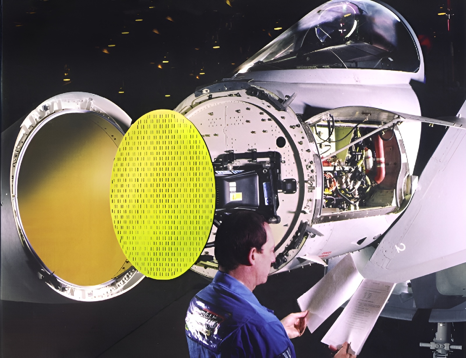
Credit: Euroradar
Nonetheless, the events on 13 April did not mark the first time that RAF Typhoons had engaged UAVs. In December 2021, the MoD revealed that the jets had intercepted a UAV flying over Syria. This marked the first time RAF warplanes had shot down a hostile aircraft since the 1982 Falklands War in the South Atlantic. The MoD revealed that an MBDA AIM-132 Advanced Short-Range Air-to-Air Missile had downed the UAV over Syria. On both occasions in the skies above the Middle East, the Captor-E had shown its ability to process small targets such as UAVs. As in the Middle East, the war in Ukraine highlights the need for look-down/shoot-down fire control radars to aid the engagement of small targets.
X marks the spot
Combat aircraft radar engineers keep the performance of their systems close to their chests for obvious reasons. Getting into the nitty-gritty of how much power a particular radar can transmit, the size of targets it can detect and at what range, is useful information to an adversary. It is these statistics that help electronic warfare engineers develop effective countermeasures to be employed against these radars. Nonetheless, some useful information regarding combat aircraft radar performance is available in the public domain. Most of these radars transmit in X-band (8.5 GHz to 10.68 GHz). All radar frequency choices are essentially a compromise, which must balance the size and speed of targets the radar must detect and the minimum range at which this detection is possible. Another consideration in radar design is a practical antenna size for the radar’s application. For example, does the radar need to be accommodated on a ship, vehicle or aircraft? Furthermore, how much power will be available to the radar? A naval, land or airborne installation may limit how much electricity the radar can draw from that platform.
X-band radars are a good compromise for combat aircraft. This waveband balances required radar resolution for intended targets, the physical space available on the aircraft for the radar and power generated by the engines. For example, the Westinghouse/Northrop Grumman AN/APG-68 series radar equipping various marks of General Dynamics/Lockheed Martin F-16 Fighting Falcon combat aircraft has a 600 mm antenna diameter. The Hughes/Raytheon AN/APG-71 radar equipping the Northrop Grumman F-14 Tomcat combat aircraft series had a 910 mm antenna diameter. Why are these measurements important? Antenna size governs the radar’s gain. Gain – measured in decibels (dB) – is a measurement of how much power a radar can concentrate on a particular point. The antenna can be thought of as a lens focusing power in a similar way to how a magnifying glass can concentrate sunlight on a particular spot. Open sources say that when transmitting on an X-band frequency of 9.59 GHz, the AN/APG-68 has a gain of 32.5 dB. The AN/APG-71 could generate 36.2dB of power on the same frequency. Contemporary Active Electronically Scanned Array (AESA) radars are said to produce 40 dB of power. The radar’s gain directly affects how much power the radar needs to operate. In this case, the AN/APG-68 needs 5.6 kW of power, but transmits a signal with 17.5 kW of strength. Matching this 17.5kW output power with the AN/APG-68’s gain gives an Effective Radiated Power (ERP) of 72.78 dB.
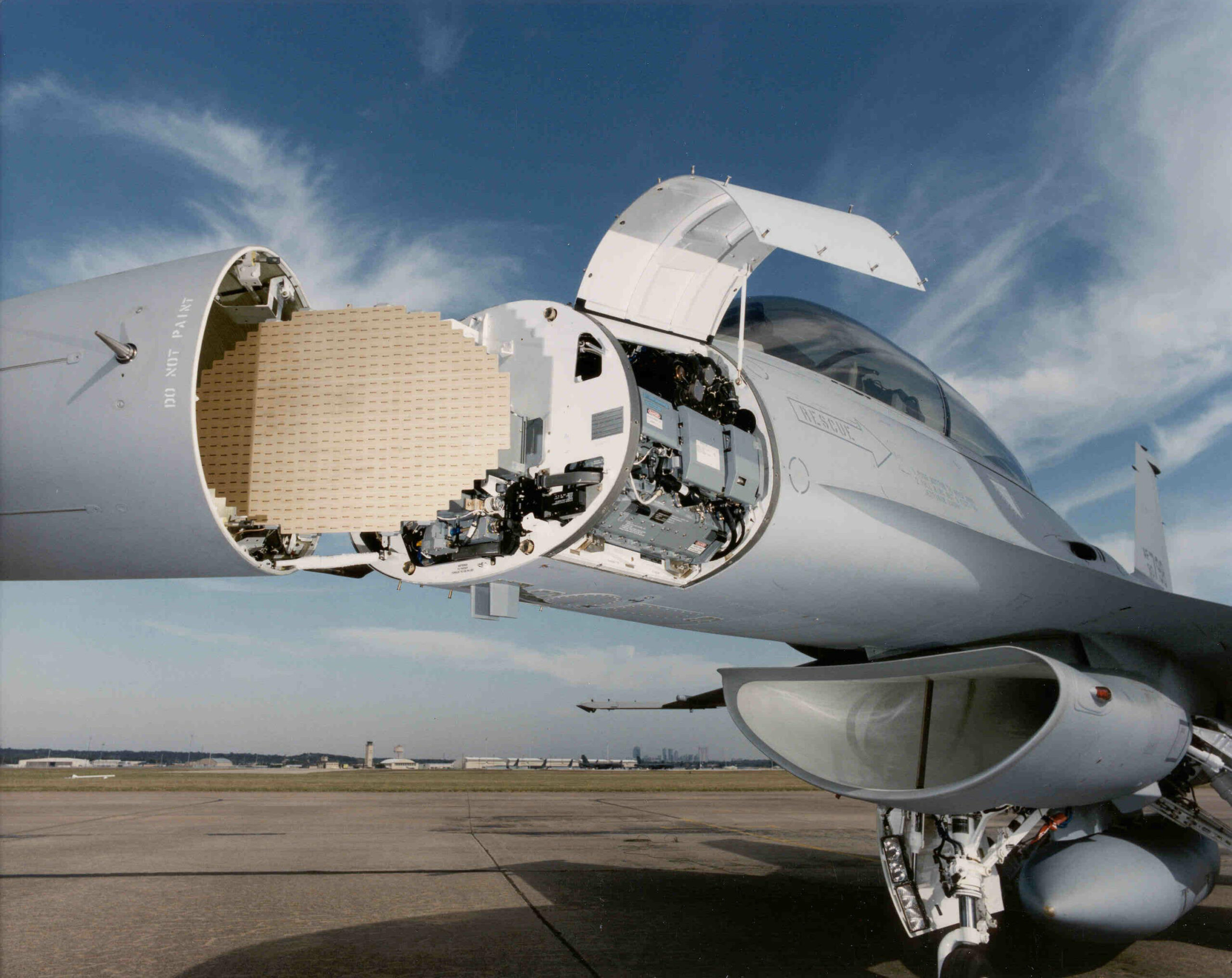
Credit: Northrop Grumman
Consider a situation where a small UAV is below and in front of an aircraft at a range of 85 km heading towards troops on the blue force’s forward line of troops. The aircraft’s radar signal must travel from the antenna through the atmosphere to the target. Like a person moving at speed through a heavy crowd, the atmosphere, and all its constituent parts, conspire to sap the signal’s energy as it travels. The signal might have left the antenna with a strength of 72.78 dB but moving through 85 km of the Earth’s atmosphere has a cost. The signal loses just over 150 dB of power, giving at strength of -77.22 dB when it hits the UAV.
Publicly available figures state that a DJI Phantom UAV has a Radar Cross Section (RCS) of 0.02 m2. RCS is an important measurement as it governs how much of the incoming radar signal the UAV reflects to the antenna. The radar signal bounces off the UAV and is returned to the AN/APG-68’s radar antenna as an echo. At that point of collision, the signal has a strength of -77.22 dB. The journey back to the radar knocks more energy out of the signal and by the time the signal reaches the radar antenna, having completed the round trip, it will have lost a further 59.48 db of power. Thus, the echo now has a strength of -136.7 db. In total, the signal has lost 209.48 db of power since it was transmitted from the antenna. This scenario somewhat simplifies matters. The signal will lose more power as it moves from the antenna into the backend of the radar for processing. The radar’s own electromagnetic ‘noise’ from its components risks masking the signal. The problem caused by such a weak echo is that this might be below the signal threshold that the radar is designed to process.
Implementing various parameters or ‘gates’ into a radar’s design makes sense. Fixed- and rotary-wing aircraft and missiles are not the only things flying through the sky. Birds are plentiful and also have radar cross sections. According to figures from the Massachusetts Institute of Technology’s Lincoln Laboratory in Lexington Massachusetts, some birds can have an RCS of between -0.02 and -0.003 m2. It makes sense to design a radar which is not going to inundate the pilot with false alarms on flying objects which could be a flock of jackdaws. The problem is that some small UAVs can have a comparable RCS to some birds. Designing a radar to ignore flocks of birds may mean that UAVs go similarly unnoticed.
Velocity gates
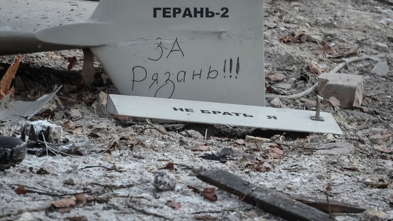
Another problem with determining a target like a UAV is velocity. A radar may employ a velocity gate which, much like RCS filtering, enables the radar to process certain targets while ignoring others. A pilot will need to be aware of some targets, but may be able to ignore others. Suppose a target has a 0.05 m2 RCS but is travelling at 3,704 km/h. Both the RCS and the target’s speed would cause the radar’s processing to classify, with a degree of accuracy, this target as an air-to-air missile. Nonetheless, a target with an RCS of 0.05 m2 could also be a large bird, such as a goose. The key discriminating factor here is the speed of the target. A goose can fly at up to 23 km/h while the missile is clearly much faster. Thus, two very different targets, a missile and a goose, nonetheless have similar radar cross sections, but vastly different speeds. The radar’s velocity gate will allow the echo from the air-to-air missile to be processed and presented to the pilot on their screen. The goose on the other hand, will be discounted as the bird’s speed is insufficient for the target to warrant further processing. The velocity gate will have speed thresholds based on the targets the pilot needs to see and to exclude the ones they do not.
Credit: Ukrainian MoD
The problem in this hypothetical scenario is that the ability of the velocity gate to accept some echoes based on target parameters and reject others could result in some targets being ignored. A DJI Phantom can have a top speed of 71.7 km/h, but to a radar, the UAV can risk looking like a goose given its similar RCS. There is a danger, that because of the UAV’s characteristics, it is ignored as a target by the radar depriving the pilot of the ability to detect and then engage this threat if necessary.
Micro Doppler processing
The solution to this vexing UAV challenge lies in either enhancing the software of legacy combat aircraft radars or ensuring that capabilities to detect targets such as UAVs are included in new systems. A clear challenge is detecting the UAV in the first instance, while reducing false alarms as much as possible. The radar must detect and track the UAV, while ignoring false targets such as birds. One potential solution lies in exploiting particular characteristics inherent in a target that includes UAVs, which tend to use several spinning rotors for lift and propulsion. These rotors will affect an incoming radar signal in very specific ways and observing these characteristics will help discriminate the UAV from a bird, for example. Flapping wings affect an incoming radar signal in a notably different way compared to spinning UAV rotors.
Determining the characteristics of a UAV’s spinning rotors can be done by using a process known as Micro Doppler processing. Doppler Shift is a key element of the physics exploited by radar. The basic principle behind Doppler Shift is that a frequency of a signal will change slightly when it is reflected by a moving target. Frequency is a measurement of how many cycles a wave performs over a set time. A cycle is the process by which a wave moves from a peak to a trough and back to a peak again. Frequency is a measurement of how many cycles the waves perform each second. A radar transmitting on a frequency of 9.59 GHz has a signal which performs 9,590,000 cycles per second. A target moving towards a radar will reflect an echo with a slightly higher frequency compared to the frequency of the original transmission, and vice versa if the target is moving away. An oft quoted example of Doppler Shift is how a moving police car siren sounds to a stationary pedestrian. As the police car approaches, the frequency of the siren seems to rise and then fall as it drives past the individual. This phenomenon occurs because the peaks and troughs of the wave take progressively less time to reach the observer as the police car approaches; Basically, the observer receives more peaks and troughs per second. The opposite process happens as the police car drives away.
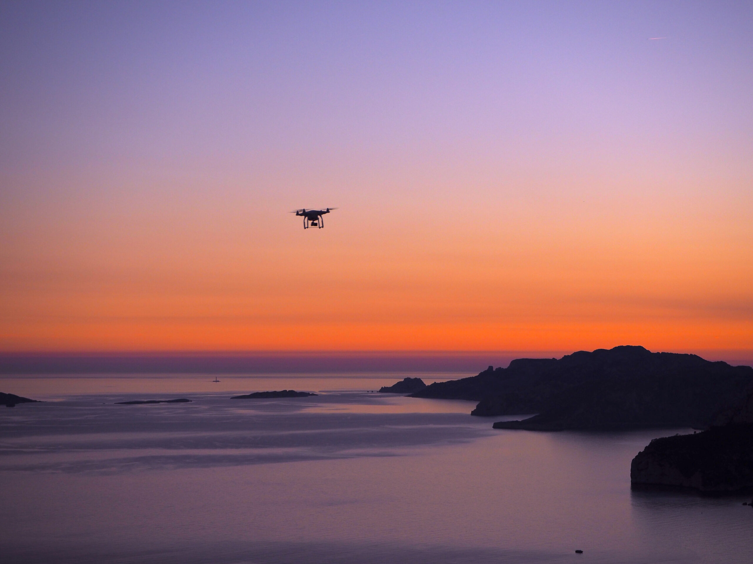
Micro Doppler processing exploits the miniscule differences in the frequency that the spinning rotors of the blades of the UAV cause. Suppose an F-16 is flying at 918.6 km/h and the UAV is flying at 71.7 km/h. The F-16’s radar is transmitting a signal with a frequency of 9.59 GHz. The moving UAV will return a radar echo with a frequency of 9.589992 GHz. The blades of a DJI Phantom UAV are circa 12 cm long with the rotors having a circa 75 cm circumference. The blades spin at between 6,000 and 12,000 rpm. These rpm rates respectively translate into speeds of 360,000 revolutions-per-hour (rph) and 720,000 rph, corresponding to speeds of between 270 km/h and 541 km/h. The speed of these blades will generate small, but noticeably different Doppler Shifts compared to the UAV itself. The Doppler Shift of the UAV’s blades spinning at 270 km/h will be 9.589994 GHz and 9.589997 GHz for blades spinning at 541 km/h. The difference between the radar echo for the UAV and the radar echo for the blades spinning at 270 km/h will be as small as 2 Hz, or 5 Hz when the blades spin at 541 km/h.
Credit: Alexei Bodorez
The difference is tiny, but it is a difference nonetheless that the radar can exploit. In addition, the spinning blades will produce a notably different Doppler Shift compared to the flapping wings of a bird. Established research says that a goose flaps its wings at a rate of 2.6 beats-per-second, producing 156 beats-per-minute. This rate is noticeably lower than the 6,000 rpm to 12,000 rpm of the DJI Phantom. If the tips of a goose’s wings move through 1 m, they will be moving at a speed of 9.3 km/h, causing a Doppler Shift of 9.589992 GHz. This is the same Doppler Shift of the DJI Phantom, but the Doppler Shift of the bird itself will also be different at 9.58993 GHz. Radar processing will be able to take these tiny changes in echo frequency generated by the spinning blades of the UAV or flapping wings of the bird to discriminate these targets. Moreover, radar processing can exploit other characteristics. For instance, the speed of the UAV’s blades will smoothly increase and decrease as the aircraft varies its lift and speed, while the flapping wings of the bird will be more intermittent. The wings will beat when the bird needs lift and speed but will be relatively still when the bird is gliding. Through noticing these potentially sudden changes in Doppler Shift, the radar can also discriminate a UAV from other similar, but false, targets.
Radars into jammers
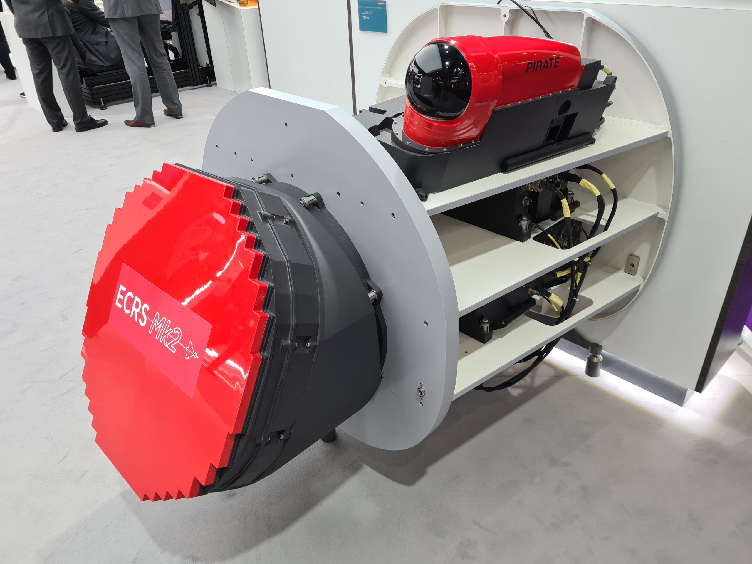
While the Captor-M has earned its spurs helping to kill UAVs in the skies above Syria and Iraq, its successor may become deadlier still, indicating another potentially potent adornment for tomorrow’s combat aircraft radars. Leonardo is developing the ECRS Mk.2 radar which ultimately replaces the Captor-M on the RAF’s Typhoons. An abbreviation of European Common Radar System, the new radar will be capable of performing electronic attack. A key change from the Captor-M is the new radar’s Active Electronically Scanned Array (AESA) antenna. Several articles could be written describing AESA attributes in detail, but one the ECRS Mk.2’s key tricks is that it can transmit jamming signals into hostile targets such as UAVs.
Open-source information regarding the ECRS Mk.2 reveals that jamming waveforms generated by the aircraft’s EuroDASS Praetorian Defensive Aids Subsystem (DASS) can be transmitted by the radar antenna. Adding this capability means that the aircraft will be able to jam electromagnetic threats in front of the aircraft. Hitherto, this has not been possible. A key AESA characteristic is that the radar can electronically steer its beams in a specific direction which can avoid having to physically move the antenna to point it in the direction of the target. Fixed AESAs typically have a conical field-of-view (FoV) of between 90° and 110°. The ECRS Mk.2 is mounted on a rotating ‘swash plate’ allowing the antenna to be physically moved, building upon the antenna’s existing electronic beamsteering to provide greater coverage in azimuth and elevation. The ECRS Mk.2 has a FOV of approximately 150° as the radar can be moved up to 30° off-boresight, according to reports.
Credit: Thomas Withington
Potentially, hostile UAVs could be targeted by the electronic attack capabilities of radars such as the ECRS Mk.2, which could remove the need to fire expensive ordnance at what are often inexpensive aircraft. However, the ECRS Mk.2 transmits in X-band (8 to 12 GHz). Most UAVs are using pilot-to-aircraft links with much lower frequencies. The Global Navigation Satellite System (GNSS) Position, Navigation and Timing (PNT) signals that a UAV receives are also much lower down the radio spectrum compared to X-band. Typically, civilian UAVs use frequencies of 2.4 GHz and 5.8 GHz to connect the aircraft to the pilot. Frequencies of 1.1 GHz to 1.6 GHz are employed to transmit PNT signals from GNSS satellites to their receivers on Earth. It is possible that the jamming efficacy of an X-band radar may be contingent on the UAV being able to receive such signals. Equally, the DASS and radar may need to be capable of generating and transmitting waveforms effective against the frequencies that UAVs rely on.
The need for look-down/shoot-down combat aircraft radars which can engage small targets, including UAVs, is as paramount in Ukraine as it will be in future theatres of conflict. This is a vexing challenge since targets with a small RCS are hard to detect and track at range, and may be confused with benign targets such as birds. Techniques including Micro Doppler processing can help overcome these challenges. AESA radars hold promise in potentially neutralising drones via electronic attack, although that will be contingent on radar design. Combat aircraft DASSs may have to be reconfigured to let accompanying radars exploit this tactic. The skies above Ukraine and the Middle East show that the UAV threat is here to stay. Combat aircraft radars will need to meet this challenge.
Thomas Withington


![Developments in strike UAVs The Flyby Jackal launches an LMM during testing. [Crown Copyright 2023]](https://euro-sd.com/wp-content/uploads/2025/07/Jackal_Crown-Copyright-Kopie-218x150.jpg)
