Almost 30 years ago, something happened that would change radar forever. The first military Active Electronically Scanned Array (AESA) radar entered service. Where is this technology heading in the future?
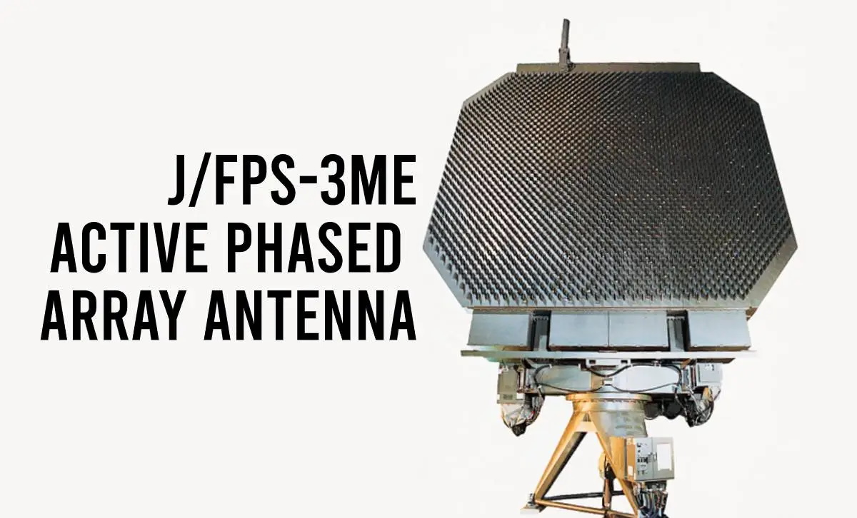
The system in question was Mitsubishi Electric’s J/FPS-3 S-band (2.3 GHz to 2.5 GHz/2.7GHz to 3.7 GHz) ground-based air surveillance radar. It was deployed with the Japan Air Self-Defence Force’s 45th Aircraft Control and Warning Group to help protect the skies over the archipelago and its air approaches. The J/FPS-3 remains in production. In October 2022 the Philippines announced it would procure three systems for USD 103.5 M which will contain improvements to the existing design. The advent of AESA technology was the culmination of years of research kick-started by the Second World War and accelerated during the Cold War. East and West raced to win the technological upper hand with this competition manifesting in part through radar design.
The Basics
Radar employs an elegantly simple principle. Radio waves, a form of electromagnetic (EM) waves, known as RF (Radio Frequency) energy to engineers, are generated in a radar’s back end and sent to its antenna. The antenna is pointed towards the area of sky, land, sea or space the operator wants to look at and the waves are transmitted from the antenna. The RF energy leaves the antenna at a particular frequency, for example, at 5.25 GHz.
These waves zoom out of the antenna at the speed of light (299,274 km/s). The RF energy moves through the ether until it hits a solid object like an aircraft or ship. This collision causes some of the RF energy to bounce back to the antenna as an echo. The radar compares the time it received the echo with the time of transmission. By dividing this time in two (to remove the time required for the return trip) the radar determines the distance to the target. Suppose the round trip of the signal is one second it will have travelled 153.9 km (83.1 NM), meaning the target is 76.95 km (41.5 NM) away.
Radars do not just calculate range, they also determine the direction a target is moving in by exploiting the Doppler Effect. We observe the Doppler Effect every day without even realising it. You may be standing by the kerbside hearing an emergency vehicle such as an ambulance coming towards you. Your ears will perceive the pitch of the siren rising as the vehicle approaches, and conversely, the pitch seems to lower as the vehicle drives away. The pitch is unchanged in reality, as the vehicle’s occupants would attest. Instead, the frequency of the sound waves increases as the vehicle approaches you and vice versa. Why does this happen? Sound waves have a similar shape to radio waves, with peaks and troughs. Frequency is a measurement of how many peaks and troughs a wave moves through each second. As the target approaches a radar’s antenna the echoes take progressively less time to arrive. This causes the frequency of the echo to increase as the target approaches and decrease as it moves away. By exploiting this effect, the radar can determine that the target is in motion and its direction. The Doppler Effect, known as Doppler Shift to radar engineers, also allows the radar to calculate a target’s speed.
The last element is elevation. A ground-based, naval or airborne radar may need to determine target elevation and hence the target’s altitude, particularly if tracking airborne targets. The radar’s software will determine the position of the horizontal relative to the antenna’s angle. It will also account for the curvature of the Earth if the target is beyond the horizon at surface level. This creates a right-angled triangle. A bit of high-school trigonometry tells us the adjacent angle is the horizontal line from the radar to the horizon. Suppose the antenna is pointed towards the sky at an angle of 17°. The invisible line drawn from the tilted antenna into the sky between the radar and the target is the hypotenuse.
Finding the length of the opposite side of this right-angle triangle determines the target’s altitude. The distance between the target and the antenna along this hypotenuse is 185 km (100 NM). The sine of 17° is 0.29 giving our target an altitude of 54 km (29.2 NM).
Arrays
These basic principles at the heart of how radars work have evolved significantly since the technology was first used en masse during the Second World War. Two historical developments were important in the development of radar technology. The first was the phased array radar which began to appear during that conflict. A phased array radar moves its beam electronically in contrast to a conventional radar which does this mechanically. The radar’s transmitter sends its RF energy to an array of elements mounted on the antenna.
Each element has a phase shifter which can change the angle at which the radar beam leaves the antenna. An analogy would be the eyes in a person’s head. Imagine that you could not move your eyes, but you could move your head up and down and side to side. You could still see around you but will have to move your head to do this. Now imagine your head is fixed, but you can move your eyes up and down and from side to side. This is akin to how a phased array radar works.
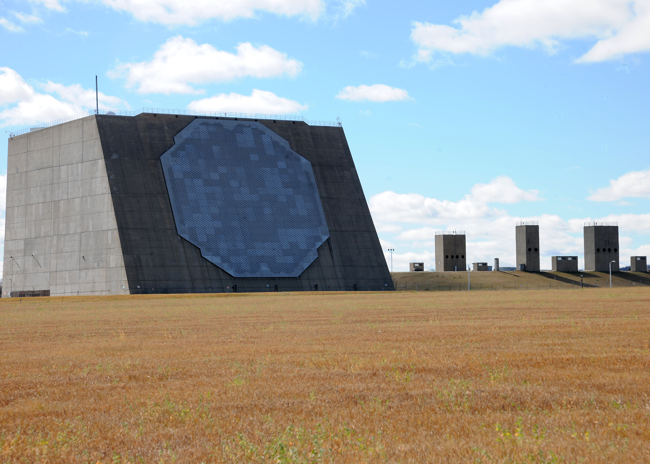
A phased array radar beam is electronically scanned from side to side and/or up and down without the antenna having to move (though the antenna can be moved to get additional coverage beyond the default field of regard). Some radars have this arrangement because they are physically very large and impractical to outfit with a mechanically-scanned antenna. An example would be the General Electric AN/FPQ-16 Perimeter Acquisition Radar Attack Characterisation System. The radar was activated in 1975 as part of the US Army’s Safeguard anti-ballistic missile system. It remains in service at Cavalier Space Force Station, North Dakota. The radar is housed in a multi-story building. It needs only to point in the general direction where a ballistic missile threat is likely to come from. In this case, the radar’s antenna is permanently pointed north to provide ballistic missile surveillance of the Arctic approaches to the continental United States.
The radar’s mission and size make it unnecessary and impractical to use a mechanically scanned antenna. Nonetheless, phased array radars do often use mechanically-scanned antennas. By combining the two technologies, the user gets the best of both worlds; a radar which can scan in a conventional pattern, or which can remain stationary to scan in a specific area. This is particularly important regarding missile defence applications. Let us assume that a conventional radar scanned through 360° once per second.
An intercontinental ballistic missile (ICBM) re-entry vehicle can re-enter the atmosphere at speeds of 6-8 km/s (15,551 knots). In the time it takes the antenna to perform a full revolution, the missile will have travelled 6-8 km (3.2-4.31 NM). This can be problematic if the radar is guiding a surface-to-air missile to intercept the ballistic missile, or an accurate assessment of the missile’s point of impact is required.
The advent of AESA technology was an outgrowth of phased array radar innovation. The latter used several elements mounted on its antenna, fed by a single transmitter. AESAs use a multitude of Transmit/Receive Modules (TRMs). Each TRM is like a miniature radar. It produces the RF energy, transmits it and processes the echo. Like a phased array radar, radar beams can be electronically scanned. However, unlike a phased array radar, the antenna can perform several tasks simultaneously, as each TRM is generating its own beam. For example, perhaps a radar must detect and track hostile aircraft approaching from the northeast, but the radar also needs to detect and track hostile surface-to-surface missiles approaching from the North.
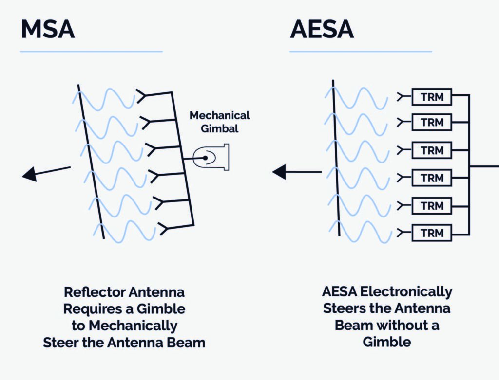
The antenna is kept stationary, and assuming both sets of targets are within the antenna’s field of regard, some TRMs can be tasked with monitoring the northeast, while another set monitor the missiles to the North.
The radar is configured to perform in a particular way by instructional software. The resulting transmitted radar signal intended to perform a specific task is known as a waveform. This waveform can be adapted to achieve the best possible RF energy return from a particular type of target. AESAs allow each set of TRMs to optimise for a given target type. Using the above example, the TRMs monitoring the northeast can tune their transmissions to optimise conventional aircraft detection, while those monitoring the North can tune theirs to achieve the best return from missiles.
AESAs offer several other key benefits compared to conventional radars such as generally better signal-to-noise ratio, improved clutter rejection, and graceful degradation. This latter advantage can be explained through an example. Some AESA radars have hundreds, if not thousands, of individual TRMs in their antennas, for instance, Thales’ RBE2 AESA radar equipping the Dassault Rafale family of combat aircraft has circa 800. If a few of the TRMs fail, the radar will still function but with only a marginal loss of performance. By comparison, if a phased array radar fails, the loss in performance can be total. Added to this, AESAs are often relatively easy to repair, with new TRMs modules slotted into the antenna to replace broken ones. Fixed AESA antennas typically also have fewer moving parts (and hence fewer points of failure) than mechanically scanned radars, although this does not apply to AESA radars which can be physically moved. For instance, the Euroradar Captor-E AESA system for the Eurofighter Typhoon combat aircraft is mounted on a mechanical re-positioner to further increase the radar’s field-of-view beyond what is possible with purely electronically scanned systems.
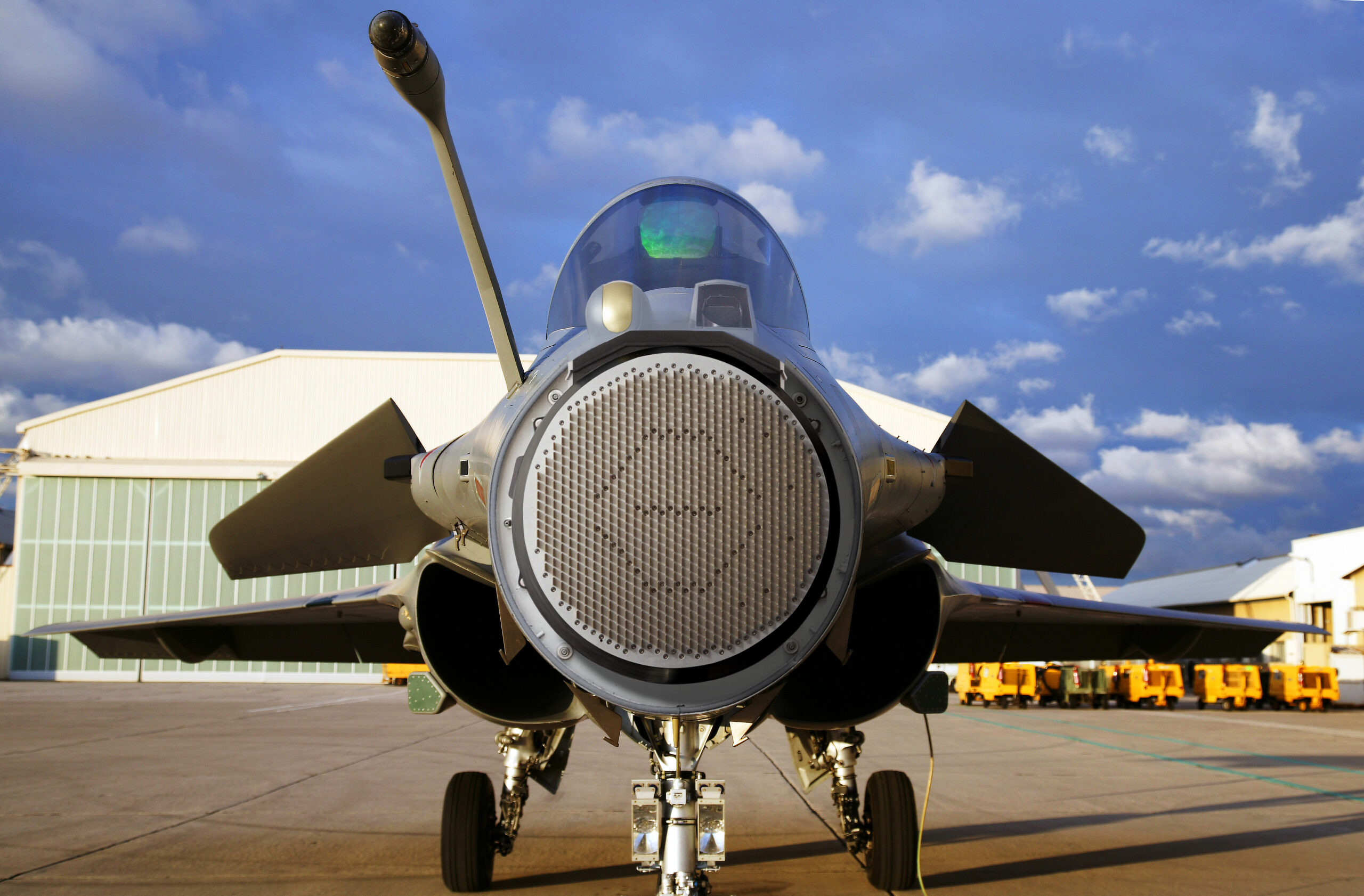
An AESA often performs what is known as a raster scan. A beam moves very quickly in a rectangular pattern, from right to left downwards in a saw tooth pattern. The radar beam itself is very narrow meaning it can depict a target in detail. This helps the radar to identify its target as a conventional aircraft or a vehicle on the ground for instance. As an AESA can generate several beams because it has multiple TRMs, it can continue scanning for targets while one, or several, beams continue to track a specific target. This saves the radar having to return to that target anew each time the raster scan starts. The process also makes the radar’s transmission behaviour less predictable.
Hostile Electronic Support Measures (ESMs) detect, identify and locate radar transmissions. Once the ESM detects a radar, identifies it as hostile, and determines its location, it can be attacked with jamming. ESMs use specific software which interpret incoming radar signals, a well-programmed ESM can even identify a particular radar equipping a specific aircraft. This is done by associating particular waveforms with particular radars. An AESA transmitting with multiple beams can act in a seemingly random way which makes it harder for the ESM to correlate a series of radar signals with a particular radar, thereby helping the latter avoid identification. Moreover, the TRMs can even make each pulse different in terms of frequency. This further frustrates the ESM’s ability to associate a collection of seemingly random signals with a specific radar.
The Future
Where do AESAs go from here and what technologies will they incorporate? Radar manufacturers are understandably coy about sharing their future innovations. Nonetheless, some indication of the direction of travel can be gleaned from information in the public domain. Four key areas are cognitive techniques, materials, architectures and cost-effectiveness.
The application of cognitive techniques to radar focuses on the adoption of Artificial Intelligence (AI) and Machine Learning (ML) techniques. In 2018, Dr. Nathan Goodman of the University of Oklahoma published a paper entitled ‘Foundations of Cognitive Radar for Next-Generation Radar Systems’. He noted that “all radar systems constantly observe the surrounding environment, inferring properties about the environment … and modifying their observation … through changing waveforms and antenna pointing directions.” Dr. Goodman argued that cognitive radar takes this further. Tomorrow’s radars will “(maintain) real-time hypotheses about the environment in order to adaptively control the form and parameters of the actual sensing procedure.”
A cognitive radar could understand what it is seeing and adapt its behaviour therein. For example, a radar could detect several vehicles are moving together. Is this an advancing column of armour? Nothing much else is happening in the rest of the radar’s field-of-view. A cognitive radar would immediately recognise the column and deprioritise what is happening elsewhere. The radar will have learned to recognise the column of armour as distinct from a traffic jam of stationary cars. Its software will have been ‘trained’ to recognise armoured vehicles by determining their speed, disposition and behaviour.
In fact, a cognitive radar’s software could be trained with numerous data to recognise certain targets or situations and to change its behaviour as appropriate. Likewise, perhaps the radar has been trained to recognise when it is being jammed. It will automatically modify its waveforms and transmission power, etc. to ameliorate the worst effects. The rationale behind adopting AI and ML techniques in radar is to reduce operator workload and improve radar efficiency. However, a note of caution should be sounded – a cognitive radar will only ever work as well as the learning data it receives. Incorrect, incomplete or corrupted data will significantly degrade performance.
Beyond cognition, we can expect improvements in the materials which radars depend on. AESAs rely on two vital materials, Gallium Arsenide (GaAS) and Gallium Nitride (GaN). The latter is progressively replacing the former, although both are routinely used in AESA TRMs. GaAS and GaN are favoured as tough materials which can handle the significant heat produced by a radar. Although GaN is in vogue for AESAs it could be progressively replaced in the coming years by diamonds, which can be grown in a laboratory, and provide excellent thermal conductivity. TRMs constructed thus could tolerate even higher operating temperatures compared to today’s AESAs, translating into improvements in radar performance and longevity. The US Defence Advanced Research Projects Agency (DARPA) has embarked on research into employing diamonds, with DARPA’s Near Junction Thermal Transport (NJTT) project having demonstrated combining GaN and diamonds in transistor design.
Using diamonds will also help make AESA radars smaller, assisting miniaturisation. All military radars must be designed with the size, weight and power constraints inherent in the platform or capability they equip. Electronics, and hence radars, are getting smaller. This is thanks to the oft-quoted dictum of Moore’s Law. Dr. Gordon Moore, co-founder of the Intel Corporation, made a prescient prediction in 1965. He forecast that the number of transistors that could be housed on a single microchip will double every two years. This broadly held true for a number of years, which is why today’s smartphones are smaller, and do more than 1980s era cellphones, however more recently such progress has declined, owing to difficulties making smaller and smaller transistors, and practical challenges such as power and thermal management.
Nonetheless, smaller radars will have two consequences. Firstly, more platforms and smaller platforms can be outfitted with high-performance AESA radars. This will enrich situational awareness to previously-unseen levels. Secondly, more radars will be able to outfit a single platform. Traditionally a combat this has one radar mounted in the nose providing a 90° to 120° degree field-of-view in front of the plane. Smaller radars could enable the jet to be covered with AESAs along the wings, on dorsal and ventral fuselages and behind the aircraft. The pilot will now be able to see what is happening through 360° around their plane, and cognitive techniques will ensure they are not deluged with data, as the radar’s software continually prioritises what they need to see.
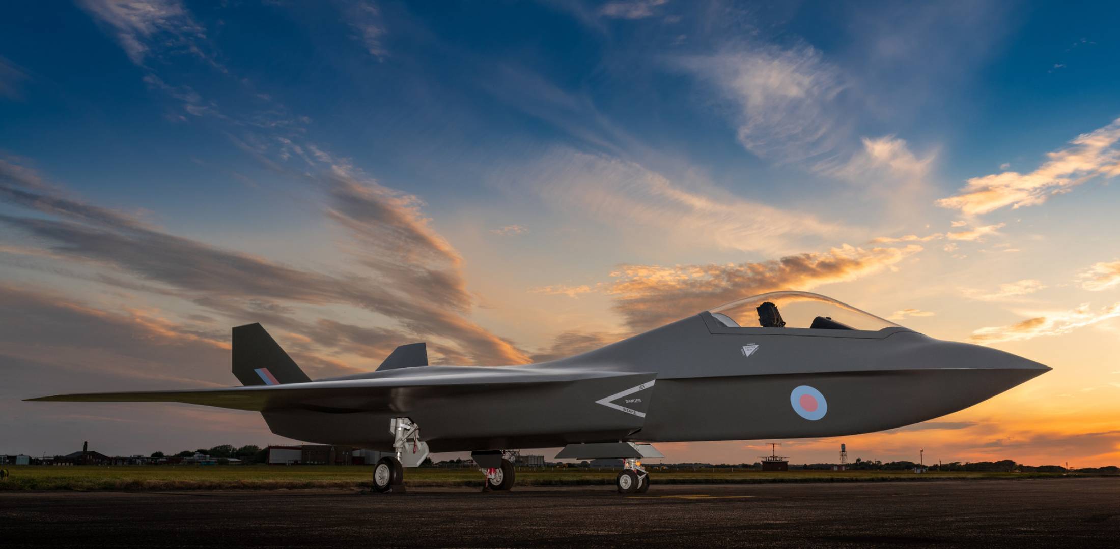
Last, but not least, we must talk about money. Many of the innovations discussed above risk increasing radar development and procurement prices further. That said, the adoption of materials like diamonds could paradoxically probably reduce radar operating costs by reducing maintenance, repair and overhaul expenses. The radar world will benefit from innovations like digital twin technology. A digital twin is a virtual model of a real-world system under development. All aspects of the system’s design and performance are programmed into the digital twin. This reduces research and development costs by eliminating the need to produce so many prototypes to evaluate numerous aspects of the design.
The first thirty years of AESA radar has been exciting. These systems are now in routine military use globally across sea, land, air and space domains. As the cost of AESAs reduce we could see this technology increasingly migrating to the private sector. The innovations discussed in this article are very much on the horizon and could become routine in tomorrow’s radars. The next three decades should be even more exciting.
Thomas Withington


![Desert tracks: The Gulf AFV market Seen here in service with the Kuwait Land Forces, the M1 Abrams family is the most numerous MBT in the inventories of Gulf militaries. [US ANG/MSgt Matthew Keeler]](https://euro-sd.com/wp-content/uploads/2025/07/01_M1-Abrams_US-ANGMSgt-Matthew-Keeler-Kopie-218x150.jpg)


