The uptake of radio frequency over fibre optic technology for use on the battlefield could increase in the coming years as land forces seek ways to mask their radio emissions from detection and interference.
Radio frequency (RF) energy exists in the radio segment of the electromagnetic spectrum, typically 3 kHz up to 300 GHz, though not all of this spectrum is used by militaries for communications. Navies, armies and air forces typically used frequencies of 3 MHz to 30 MHz for high frequency (HF) radio which can transmit across intercontinental ranges. HF does this by aiming signals at an angle against the ionosphere, an ion-rich layer of the atmosphere positioned between 48 km and 965 km above the Earth’s surface. HF signals cannot penetrate the ionosphere, meaning that they are bounced back to Earth. If these signals are transmitted towards the ionosphere at an angle, they will be refracted to Earth at a reciprocal angle. This process explains how HF signals can avoid the curvature of the Earth.
Very and ultra-high frequency (V/UHF) signals between 30 MHz and 3 GHz are typically used for line-of-sight (LOS) communications. It is largely pointless to aim these at the ionosphere as they will move through it and off into space. Instead, V/UHF is mainly used for LOS traffic. This means that the antennas of two or more V/UHF radios need a mostly unobstructed LOS between them to communicate. There is a notable exception to this rule. Tropospheric communications use signals of 3-30 GHz to achieve beyond line-of-sight ranges. Much like HF, signals using these frequencies are aimed at an angle through the troposphere. The troposphere is the lowest level of the atmosphere typically reaching altitudes of between 6 km up to 18 km). A lot of moisture is found in this layer which causes tropospheric signals to be refracted over a large distance and captured by receiving antennas. Militaries also use satellite communications (SATCOM) signals which are beamed to a satellite and then transmitted back down to their intended recipients on Earth. SATCOM frequencies also have their own distinct advantages and disadvantages.
Militaries use so many different types of radio communications primarily because no system is perfect. HF is excellent at travelling across intercontinental distances but offers very low data rates. To put things into perspective, HF can handle around 4.8 kbps of data. By comparison, a smartphone can handle about 100 Mbps. V/UHF carries much more data but lacks a beyond line-of-sight range. That said, Comtech, a company specialising in troposcatter (tropospheric scatter) communications, now boasts troposcatter terminals that offer speeds of up to 210 Mbps. Choosing the right military communications conduit is an exercise in visualising the task at hand and the respective acceptable trade-offs in performance.
Detection risk
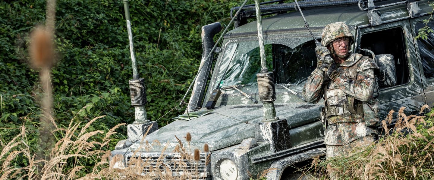
Another concern for militaries is that radio signals propagate through the air, or through space, and some can even travel through water, particularly at very low frequencies of between 3-30 kHz. As we know ourselves from using our smartphones, if a radio wave can travel through the air it can be detected. Radio propagation through the air risks making military communications vulnerable to detection by an adversary.
Credit: Rohde and Schwarz
Radio engineers undertake an array of steps to try to mask communications signals from detection. These steps rest on two fundamental principles: Firstly, making the signals as hard as possible to detect. Detecting the signal carries two major risks on the battlefield: If the signal can be detected, it is possible to locate the signal’s source relative to one’s own position. Locating the transmitter can take the form of a bearing, for instance, the transmitter is on a bearing of 260° from a specific location. If two or more radio receivers are involved, the location of the transmitting antenna can be triangulated. Most personnel, vehicles, ships, aircraft, bases, platforms, sensors and even individual weapons depend on radio communications. Find the radio, and you find the troops, base or platform. Once location is determined, the target can be engaged by fires or manoeuvre. Finding these assets may also help ascertain the size and strength of hostile assets deployed in the locale.
Secondly, if signals can be detected, that means they can be intercepted. Interference can take the form of jamming to stop a signal reaching its destination. Hostile radio signals can also be intercepted with the purpose of implanting false or misleading traffic into a hostile communications network. Hostile radio networks can also be hacked with signals carrying malicious code. Nearly all military assets rely today on some form of computing which in turn relies on code being carried across military networks. Hostile zeros and ones can wreak havoc on the battlefield.
RFFO
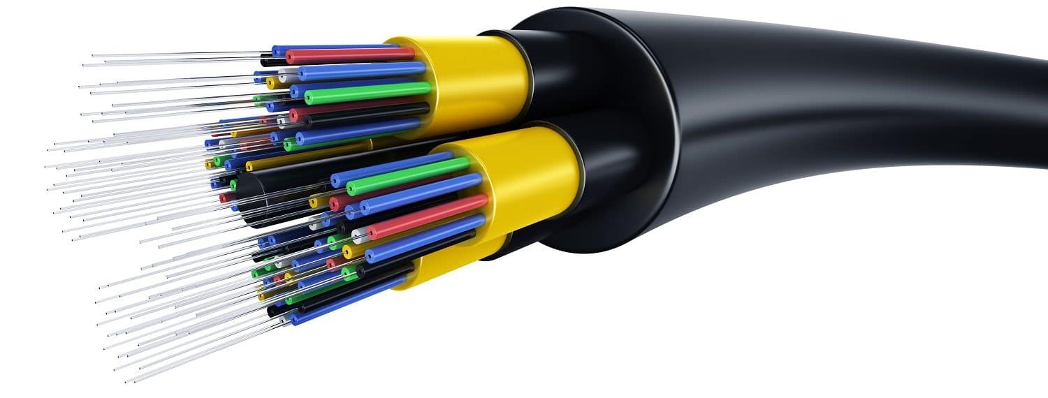
Alongside the steps engineers take to reduce the chances of radio signals being detected and attacked, land forces can employ other measures to shield their communications traffic against interference. Radio frequency over fibre optic (RFFO) employs a relatively simple concept. The technology uses flexible glass or plastic to transmit light signals (typically infrared). The RF is encoded into data which is then encoded into a light signal at one end of the fibre optic cable. The light signal travels through the glass or plastic tube. The light moves around corners and obstacles by bouncing off the interior walls of the cable as reflections. At the traffic’s destination, the light signals are decoded back into data and then back into a radio signal. Radio waves and light travel at the speed of the latter; around 299,274 km/s. When light is travelling through a medium such as glass or plastic, this can reduce to around 197,520 km/s. A report published by Huber and Suhner, which produces military RFFO links, say that these can be used to create wired links of up to 100 km.
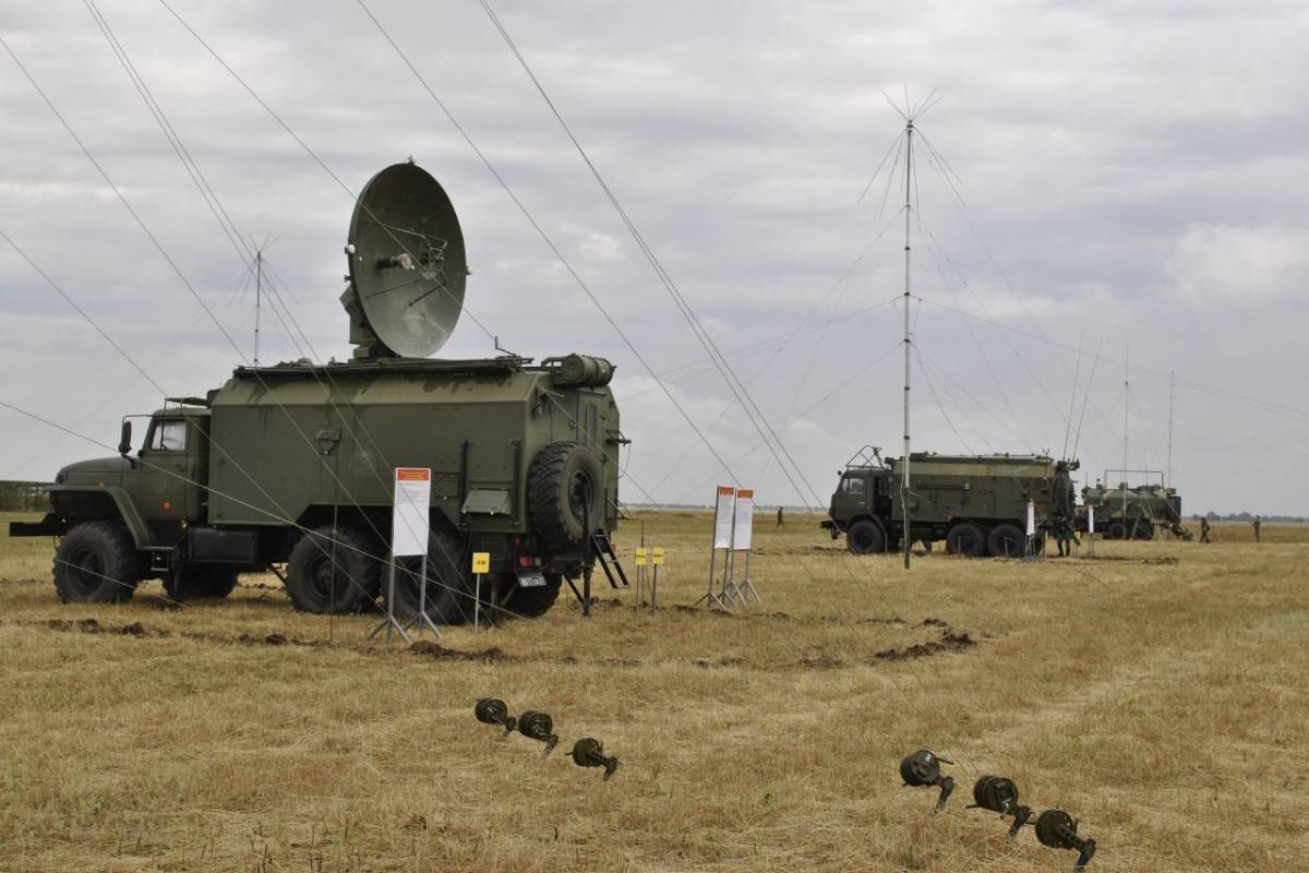
A key consideration for military communications planners is RF loss rates. All radio signals lose energy as they move through the ether. The greater the distance a signal must travel, the more energy it loses in the process. A radio signal with a frequency of 300 MHz can lose up to 98.9 dB of signal strength when travelling across a 7 km range. If a radio transmits 5 W of power and has 3 dB of gain, a signal with a strength of 9.9 dB at the radio’s antenna will be produced. Gain is a measure of how much energy an antenna can focus in a specific direction. We must take this figure of 9.9 dB and subtract the loss rate of 98.9 dB giving us a total of -88.9 dB signal strength at the receiving radio. A general rule of thumb in radio engineering is that the closer a loss rate is to zero, the stronger the signal is.
Credit: Russian MoD
High loss rates are problematic on the battlefield. Firstly, loss rates can affect the fidelity of the signal reaching the receiving antenna. Fidelity losses can affect the quality and integrity of the voice or data traffic carried by the signal. Secondly, a weak signal can be vulnerable to jamming. There is a general rule of thumb in electronic warfare that if you want to jam a radio or a radar, you jam its receiver. Radars and radios generally use the same antenna to transmit and receive. The reason for jamming the receiver is because a signal is weaker when it is being received than when it is being transmitted for the reasons stated above. Quite simply, one needs less jamming power to drown out a signal that is being received. By using a relatively powerful jamming signal, a radar or radio can be inundated with electronic noise. This inundation hampers the radar or radio’s ability to ‘hear’ the signal it is supposed to be receiving. In our example above, a 300 MHz jamming signal aimed at a radio’s antenna with more power than the -88.9 dB received signal should be enough to ‘wash out’ the genuine signal the radio is trying to receive.
As RFFO moves the signal through a cable, the signal itself should be immune from significant loss and jamming, given the medium it is passing through. Electronic warfare relies on a signal moving through the air, or through space, to do its work. When a radio signal is passing through a cable it is much harder to exploit. Moreover, the composition and behaviour of Earth’s atmosphere can have an impact on how efficiently radio signals move from one place to another. Huber and Suhner’s report claims loss rates of up to 6 dB/km when using RFFO. This would compare favourably with the aforementioned example radio signal, with calculations showing a cumulative loss rate of circa 14.1 dB/km when transmitting the signal through the air. The comparatively low loss rates heralded by RFFO also enable traffic to be carried across long distances without repeater stations – though these stations may be needed to boost the signal when using conventional copper cables, as the signal loses power when moving through the wires.

Credit: ACAL BFI
Applications
Distances of up to 100 km mooted for defence RFFO applications could make the technology practical for military trunk communications. Fibre optic links are already extensively used by integrated air defence systems (IADSs). IADS typically link powerful ground-based air surveillance and fire control/ground-controlled inception radars to command centres. The command centres and radars may be separated by very long distances, sometimes even hundreds of kilometres. Radars will generate rich pictures of the airspace they monitor, together with detailed track information on the targets they detect and follow. The high bandwidths offered by fibre optic cables allow these pictures to be shared in impressive detail. At the command centre, recognised air pictures (RAPs) from numerous radars sending their imagery are federated. By federating this imagery, command centres can build a detailed RAP of the locale under their control. It is possible to share these pictures across conventional radio and SATCOM links. That said, these could be vulnerable to jamming or other forms of interference such as eavesdropping. In practice, many IADS use several types of links to connect their elements, including fibre optics, to ensure redundancy.
The uptake of RFFO technology for use on the battlefield seems destined to increase in the future. Firstly, RFFO allows static command posts to be networked with relative ease. Wired connectivity is thus facilitated with recourse to field telephones. Instead, the standard transceivers that headquarters use for tactical communications could also be networked with RFFO cables. Granted, using this technology makes no sense for manoeuvre units which must remain mobile and ready to move at short notice. Nonetheless, a deployed headquarters moving less frequently could be networked with higher echelons using RFFO links. Uninhabited aerial vehicle (UAV) operations could also benefit from RF over fibre links. Pilots communicate with their aircraft using radio and vice versa. The antennas the pilots depend on are often co-located with the pilot’s ground control system (GCS). As with all radio communications, this creates a risk. The pilot’s position could be ascertained by geolocating the source of the radio emissions connecting them with the UAV. A key lesson of the ongoing war in Ukraine is that a UAV pilot’s position can be determined by their radio emissions to the aircraft, with the pilot’s location then engaged by artillery. Antennas connecting the pilot and their GCS to their aircraft could be linked using RF over fibre cables. Even if the antenna’s location is determined and engaged by fires, as it is some distance from the pilot’s position, the latter may still have a reasonable chance of survival.
Credit: Lynx Broadband
RFFO is a niche technology. There will be many situations where it is still essential to transmit radio signals through the ether. Moreover, RFFO offers promise in situations where a wired connection can make sense. Turning radio signals into light and sending them down a cable can help prevent signal detection and interference. On a battlefield where the detection of a radio signal can invite attack, RFFO technology has clear potential.
Thomas Withington


![Pilots for soldiers A US Soldier assigned to 2nd Brigade Combat Team, 101st Airborne Division operates the Kraken during exercise Spectrum Blitz 25 at the Hohenfels Training Area, Germany, on 11 April 2025. [US Army/Sgt Collin Mackall]](https://euro-sd.com/wp-content/uploads/2025/09/Spectrum-Blitz-25-US-ArmySgt-Collin-Mackall-Kopie-218x150.jpg)
![Doing everything at once This image gives a good indication of how many RF antennas a modern combat aircraft must have; these are just for the plane’s electronic warfare system. [BEL]](https://euro-sd.com/wp-content/uploads/2025/09/BEL-EW-Suite-Antennas-BEL-Kopie-218x150.jpg)

![Connect-4 The European Super RAP developed by NATO’s ACCS is shared with NATO’s Allied Air Command headquarters in Ramstein, western Germany. Two CAOCS, controlling NATO airspace above northern and southern Europe, generate these RAPs. [NATO]](https://euro-sd.com/wp-content/uploads/2025/06/NATO-Allied-Air-Command-NATO-Kopie-218x150.jpg)

